How many times have you looked at
that dead servo on the corner of your bench and wished that you
did not have to buy another?
I had 6 dead servo's that I
picked up cheap through E-Bay, all were mechanically sound, it
appeared that the previous owner had fried them with too much
supply voltage. They were a mixture of Futaba, Hitec and Acoms
servo's. After stripping them all to check that they were ok
mechanically, I looked through my other servo's for one the had
the simplest circuit to replicate, this ended up being the GWS
Premium Servo.
The main reason for this was that
the components were easy to get in Australia. I tested the GWS
Circuit with all the servo's first to check that it worked.
Construction
To build this circuit you will
need to be able to make Printed Circuit boards, if you can't then
you will need to learn how to and set yourself up with the right
equipment.
The circuit board was a cut down
replica of the GWS board. The copper side layout is shown below;

Note; This is
shown a lot larger than it needs to be the proper size for this is
17 x 16mm.
Firstly start by making the PCB
as per the layout above. Once you have made the PCB. You can start
installing components into the PCB and soldering them on. The
components you will need are;
Parts List - Servo Controller
Item Description
C1 0.01uf Ceramic Cap
C2 0.01uf Ceramic Cap
C3 0.01uf Ceramic Cap
C4 22uf Tantalum Cap
C5 22uf Tantalum Cap
C6 0.1uf Tantalum Cap
C7 .47uf Tantalum Cap
R1 22k 1/4 Watt
R2 820 ohm 1/4 Watt
R3 470 ohm 1/4 Watt
R4 39k 1/4 Watt
R5 330k 1/4 Watt
IC1 M51660L
Mitsubishi (Oatley Electronics has these)
IC2 BC640 PnP Transistor (The original was a HE5550)
IC3 BC640 PnP Transistor (The original was a HE5550)
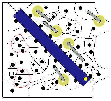
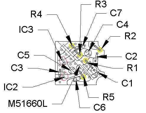
The following two diagrams show
the layout for the components into the PCB (this is a top view of
the PCB);
The first diagram shows the
polarity of the components;
The next identifies each of the
components and there location;
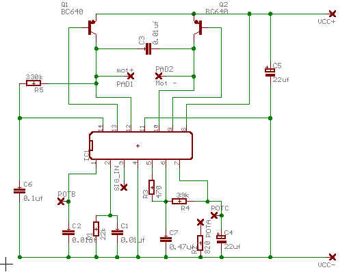
The schematic for the circuit is
shown below;
Hooking it up
Once you have got the PCB and its
components solder in and you have double checked that you do not
have anything in the wrong way and that there are no tracks joined
as a result of soldering in the components. You can now move on to
the hook up to the servo.
All of the servo's I have fixed
have had a 5k Pot to sense the position of the output shaft of the
Servo. The circuit is designed around this and you will need to
check that the Pot in your servo is 5k. To do this remove the pot
from the servo housing and them place a suitable resistance meter
across the two outer most terminals of the pot.
Check the reading, if it does not
read around 5k, then you may not be able to use this circuit. I
have never had to worry about this, however you can still try it,
if it works let me know.
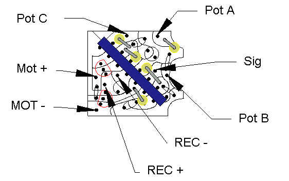
There are seven hook up points;
The only thing that will happen
if you get them wrong is that the servo will not respond correctly
to your commands and when you power it up it will wind all the way
to one side and stay there. If this happens then reverse the
connections to Pot A and C and all should be fine. Pot B is always
the middle.
To hook up the motor + and -, you
simply need to look at the back of the servo motor and there will
be a red dot on the positive side. Hook this to the Mot + and the
other to the Mot -. Some servo's have and additional capacitor
across the terminals of the servo motor, you can remove this if
you want, the circuit has a capacitor on the PCB to do the same
job.
Hook up the SIG, Rec + and Rec -
wires as shown.
Now check that you have not
soldered over the tracks and that all components are in the
correct spot. Also use a Multi-Meter set at a low Ohmage and test
on the backside on the PCB to make sure nothing is shorted out.
You can use the schematic as a guide to which parts of the circuit
should be connected to which other parts.
If you get a connection between
to tracks, double check everything.
After you are sure that is is ok,
then;
- Remove all servo drive gears
from the servo, making a note of how they came off and where
they fit (take a photo if you have a digital camera). This
should only leave the drive gear from the Servo Motor and the
pot shaft left in the servo.
- Place the output drive gear on
the Pot shaft as it would be normally.
- Take a spare battery pack and
through a connect it directly to the servo. You will need and
adapter to do this, I just use short bits of left over wire
from the resistors to make the bridge. Please make sure you
have the polarity right i.e.; Black servo wire to the negative
side of the battery and the Positive Servo wire to the
positive side of the battery.
- If all is correct the servo
should spin a little and then stop. If this does not happen
double check every thing again and if it still does not
happen, check the signal wire from the servo to make sure
there is no voltage on it. If there is you have a problem and
you need to check again. If not then you should be safe to
plug it into the receiver, as some servo's don't spin when you
hook them to the battery.
- If all is ok then unplug the
battery and plug the servo into the receiver and then plug the
battery in. If nothing happens except a little spin of the
motor then all is fine so far. If something else happens, go
back and check again.
- Now turn on your Transmitter,
the servo should start to spin immediately, if it does not
turn the output gear all the way in one direction. If the
servo starts to spin, all is well, if not then unplug every
thing and check again.
- You will find that if you turn
the output gear from right to left, there should be a spot in
about the middle that the servo slows down and it should stop.
If it does this you have done a great job as this is what
should happen. If it does not then you need to go back and
check again.
- If all is ok then you can
re-assemble the servo putting all gears back into place and
placing the circuit board into the servo case. Make sure that
the components on the PCB do not cause the connections to the
pot to short out etc.
- Double check that all is well
and then screw the covers back on the servo. It should now
look like it is a real servo.
- After you get the this stage,
then replug the servo onto the battery and check that it still
move a little.
- If it does then plug it into
the Receiver and attach the power to the receiver, it should
move, if it does good, if it does not then check again to make
sure every thing is ok.
- Turn on the transmitter.
- If the servo moves a little
and stops, this is good. If it moves all the way around to one
side and stops, this is bad. If it does this then the wires on
the pot are on the wrong way, you will need to reverse Pot A
and Pot C.
- If all is ok then move the
stick for the channel that the servo is plugged into. it
should move and operate normally. if it does not then you have
to go back and check.
I have repaired 6 servo's this
way and they all work and are still working (over 6 months). I
would suggest that you take several precautions when you first use
your repaired servo.
I hope this is as of as much
benefit to you as it was to me, if you have comments, suggestions
or anything else to say about this, please contact me.
Terms of Usage
This information
can be used only for non-commercial purposes, it can only be used
for commercial purposes with the written approval of the Author.
It can be freely distributed as long as reference is made to the
author wherever it is displayed or used. The Author takes not
responsibility for any inaccuracies in this document and also for
any loss, damage or injury the information presented here may
cause. If you have a all correction, contribution or suggestion
that you wish to share with the Author, please send an email to craig@willingtons.com
replies will not be guaranteed.